Old School Tablets
by Maj Mike Hanson
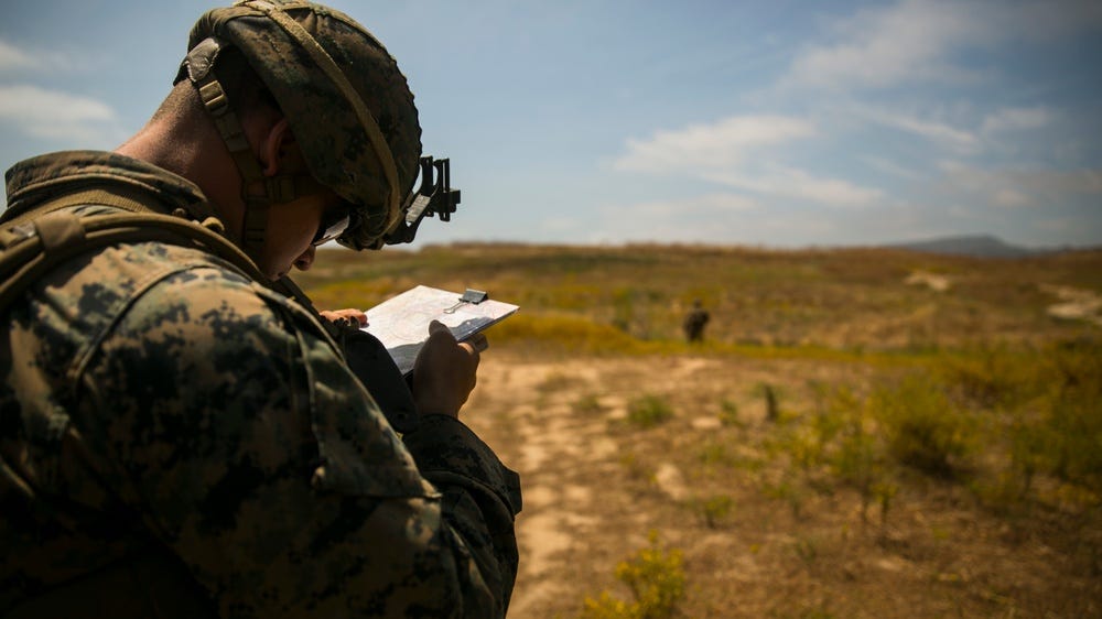
These days Killswitch, ATAK, MAGTAB, and other devices are ubiquitous across the Force. These tools are fantastic and allow Marines to plan and execute a range of operations with much more detail and accuracy than ever before. But what happens when the enemy or the elements kill your tablet? The wonders of modern technology are not immune to the effects of bullets, shrapnel, heat, humidity, water, and freezing temperatures. Whether you are technology averse or a tightwad (like myself), or just someone seeking redundancy, there is another option: a map and protractor. And that’s right, the old-fashioned way still works quite effectively as well, so well, that as a Battalion Fire Support Coordinator, I relied on maps and protractors over digital means. What worked up until a decade ago, still works.
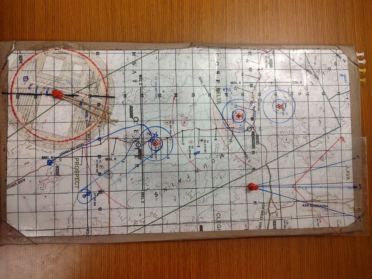
What follows is a bit on how to do simple, yet effective, map work with protractors, map pens, and push pins that allow you to rapidly maintain awareness without concern for technical glitches and failure.
Setting up your Map
First, you need a backboard because you will be inserting push pins into the map and they need to stay in. You want something that is thick enough that the tip of the pin doesn’t go all the way through and poke you. You also want something that will last a long time, imagine the effects of hundreds or even thousands of holes being poked in it.
Cardboard is not very useful because it is too thin (pins will poke all the way through) and after being poked near the same spot many times the cardboard falls apart. Though I have used cardboard in instances of short duration, there are better materials. Cork board is preferred to cardboard, but eventually it falls apart after being poked so many times near the same spot.
The best backboard is the styrofoam that comes in MK-19 cans. There are two types, squishy foam and hard foam. Both will work, but the hard foam works the best.
Now that you have a backboard, cut the map to fit the board. Obviously, you will need to cut it so the part of the map you need is in the center of the board. Quite often, a single piece of backboard is big enough but sometimes it is not. If this is the case, you can tape two pieces together so they open and close like a book. I have also seen triple sized folding boards.
When using tape for this, use duct tape. You can tape other maps to the back of the board or you can use that space for workspace. Determine if you need something mission specific or prefer flexibility prior to choosing. Consider including:
Reference tables for friendly/enemy weapons systems
A fillable target list worksheet
Timeline from a scheduling worksheet
Or even a laminated piece of blank paper that you can use to write notes on.
Lastly, the edges are a handy place for the pins you will use. Red, green, and blue colored pins will be used to track units in constant movement eliminating the time needed to continuously draw and erase positions.
And don’t forget about a great tool called Caltopo, which we have written about previously. You can create your own relief maps at the appropriate scale and laminate them to your battle board.
Setting up your Protractor
The protractor is an outstanding tool that has many under utilized functions. For these techniques to work best though, you need a round protractor.
Using white out, paint the backside of the compass scale (degrees) and the grid square scale you will use (1:50 or 1:25 usually). Then use a different colored map pen and go over the back azimuth compass scale so it contrasts with the white out. The purpose of these steps is to quickly reference azimuths, the white out enables your eyes to see the numbers by preventing them from blending in with the map. The other color makes it easy for you to quickly see the back azimuth scale. However, don’t use white out on the back of the range scale in the center of the protractor because you will need to see what is behind it to measure the distance.
Next, apply the Grid-Magnetic angle to your protractor by drawing a line on the compass scale from the GM angle, through the index hole in the center of the protractor, all the way to the back azimuth. This enables you to simply index the protractor by aligning that straight line with eastings on the map, saving you from having to do math to convert GM angles.
You can also insert strings into the center hole and tie them tight enough that they are taught against the edge of the protractor. Utilize four strings for this. When plotting CAS attacks, two can be aligned to the compass scale for each final attack heading to display the final attack cone for ingress and align the other two strings to their respective back azimuths to display the cone for egress. These cones will display where bombs that fall either short of the target will land. Aligning a tool that displays 45 degrees to each reciprocal azimuth (back azimuth) shows the ricochet area that can be expected for gun attacks along those headings. Finally, these cones also show the flight path of the aircraft for deconfliction with other assets. These strings often wear out and break. I have used rubber bands, though these wear out even quicker. The strings inside 500 cord last the longest, though you’ll have to put a knot exactly on the edge of the protractor as these strings don’t stretch.
Next, the range scale in the center of the protractor can be very handy for plotting the max effective ranges of both friendly and enemy weapons systems. Simply mark the scale at the appropriate distances in blue or red map pen to mark friendly and enemy weapons ranges. Then use the push pin to poke a hole in the scale where each distance is marked. More to follow on why shortly.
Lastly, the range scale is extremely useful for depicting Minimum Safe Distances (MSDs) for mortars and artillery. According to the DA-PAM, the Minimum Safe Distances for 60mm mortars is 250m, for 81mm mortars is 400, and for 155mm artillery is 1000m. As you did with the push pin to poke holes for the max effective range of direct fire weapons, use the push pin to poke holes on the scale for indirect fire MSD’s. When poking the holes, ensure they are large enough for the tip of a map pen to fit through. Also, ensure you poke a hole at 0m because you will need to use this hole as well. For this, I use the other side of the scale that depicts distances in 1:25,000. Just remember, even though you are using the 1:25,000 side of the scale these holes are in accordance with 1:50,000 scale. This is why I recommend having completely different protractors set up for each scale.
Now comes the best part, depicting the effects of weapons. When depicting the ranges of direct fire weapons, put the push pin into the hole at 0m on the scale and then insert the pin into the map on the location where that weapon is emplaced. Then stick the color map pen you are depicting (blue for friendly and red for enemy) into the hole for the weapon and draw the line. The push pin inserted into the map board will hold the protractor in place allowing you to stencil an arch on the map showing the range of the weapon.
For easy reference you can then label that threat wing with the type of weapon and range. For IDF and fixed wing bomb MSD’s, insert the push pin on the target or point of impact and do the same thing but trace the arch all the way around until the lines meet. You will see a perfect circle around the target. This circle is the MSD for that type of ordnance.
You can even use this technique to depict the gun target line buffer for mortars. Draw the MSD around the target and draw an MSD around the firing position and connect the outer parts of the rings. You will see the area to be avoided to prevent overhead fire. The only inaccurate part is the base angle from the firing position, but this can be plotted in detail with the protractor. This technique is useful when the GTL buffer is needed quickly, such as when a maneuver element is closing with an objective.
Additionally, I often built my own SDZ to graphically depict 15 degrees for Minimum Safe Lines and 45 degrees for Ricochet fans. This was useful for plotting the effects of supporting agencies, like tanks, CAAT, or SBF positions. Take a piece of laminate sheet and draw a long, straight line on it. This represents the Gun Target Line (GTL). Then measure and draw 15 degrees off both sides of the start point on this line and this shows what 15 degrees looks like along the length of the GTL. Lastly, about halfway up the GTL, measure and draw 45 degrees on both sides. The point of the GTL where these lines diverge is the impact point and the 45 degree lines depict the ricochet fan, where the effects of ricochets can be felt.
Pay it Forward
I learned these simple techniques in my first month at TTECG from my senior Coyotes and have used them ever since. As a Company Commander, I taught my Lieutenants these tricks with the instruction that they teach their SNCO’s and NCO’s. They were excited to learn and excited to teach this as well. I soon began to see modified protractors and map boards all over the company spaces, and that made me happy. As jammed packed as most POIs are at infantry MOS schools and advanced courses, this technique does not take long to train to, and forces developing infantrymen to understand foundational principles of direct and indirect fire support control measures and the effects of our weapon systems. Hopefully these techniques will serve you and your Marines well - especially when the batteries die and the screen cracks!
Mike Hanson the OIC of the Platoon Tactics Group at The Basic School. He can be reached at michael.a.hanson@usmc.mil.


There is wisdom in the old ways and the path to mastery is gated by understanding how your tools work.
Just like skivy shirt being the best cleaning rag the world has ever know, the Marine Corps gods provided us with the materials before we even knew we needed them, in this case, the packing foam from a MK-19 can.